Unicycle Project
Lester Vecsey
1 Overview
Design a unicycle that is for the most part 3d printed. It is split into pieces so that you don’t really require a large format printer.
Some parts can be made from carbon fiber, such as structurally for sections of the wheel, with more of a plastic for the tire.
Bearings are ceramic and are sized to be from a skateboard / inline skating.
There are also some extra features that can be added such as an onboard Raspberry Pi, Lithium Ion battery cells around the seat post, and a speed sensor.
2 Software
Here is a brief list of software used throughout the progression of this project.
2.1 Modeling
2.2 Visualization
-
Povray for visualization
-
meshlab
2.3 Slicing
Cura, and slic3r.
3 Workflow
In general the workflow is to model the parts, export .stl files, and then slice these files into .gcode.
4 Item breakdown
Certain components are purchased ready made, however in a later iteration some of them could also be customized as 3d prints too.
-
CNC machined downhill mountain bike pedals (left, and right threaded)
-
Unicycle seat, with optional front handle or grip.
-
Bearings (ceramic)
-
Metric fasteners for assembly, such as M5 screws.
Printable parts
-
Axle with barriers or dividers for where the bearings are placed.
-
Two large discs or plates with holes punched out of them that are fixed to axle, forming central region of wheel.
-
Non-standard cranks which are just fastened or attached to the axle.
-
Collet style left, right clamp around the bearings, extended into a frame.
-
A triple clamp type of piece at the top of the two side frames
-
Seat post stem, optionally modeled to support lithium ion cells.
-
Central rods (4) that interconnect and support the plates.
-
12 sectional pieces of the wheel and tire, printed from dual filament.
Ideally the Axle, and two large plates could be printed as a single joined part.
That leaves 6 remaining types of parts to print.
5 Assembly
Begin with the unified axis / plate unit.
Slide on the bearings, collet clamps (frame sides), and cranks.
Place a metric fastener into each collect clamp, tighten it and torque it down.
Attach the triple tree, and seat post stem.
Screw on and torque down the standard sized mountain bike pedals.
Attach the fancy carbon fiber seat.
6 Bill of Materials (BOM)
| Description | Store | Price (USD) |
|
|
|
| CXWXC Sealed Bearing Mountain Bike Pedals Flat Platform Bicycle Pedals CNC Aluminum Alloy BMX City | AliExpress | 23.80 |
| Exceed Carbon Unicycle Saddle - Black | Unicycle.com | 250.00 |
| Size: 8mm x 22mm x 7mm ( Inner x Outer x Thickness) black ceramic bearings | Amazon.com | 12.90 |
| Metric fasteners (assortment) M2.5, M3, M4, M5, etc. | Amazon.com | 19.99 |
| 24 additional M8 bolts for wheel, length is 20mm | | |
| |
Tax not specified. The pedals from AliExpress have a shipping fee, and the unicycle seat has a shipping fee.
7 Prototype images
7.1 Current
Another idea is to use Meshlab software to pattern each quad face with some fractal terrain.
This is shown already in this preview of an assembly picture.
7.1.1 Outer frame
7.1.2 Receiver hub
7.2 Prototype models
The prototype is for a 24” wheel with a 3” tire.
These are .STL files for use with your slicer such as Cura, etc.
unicycle_stlpack.zip
7.3 Test parts
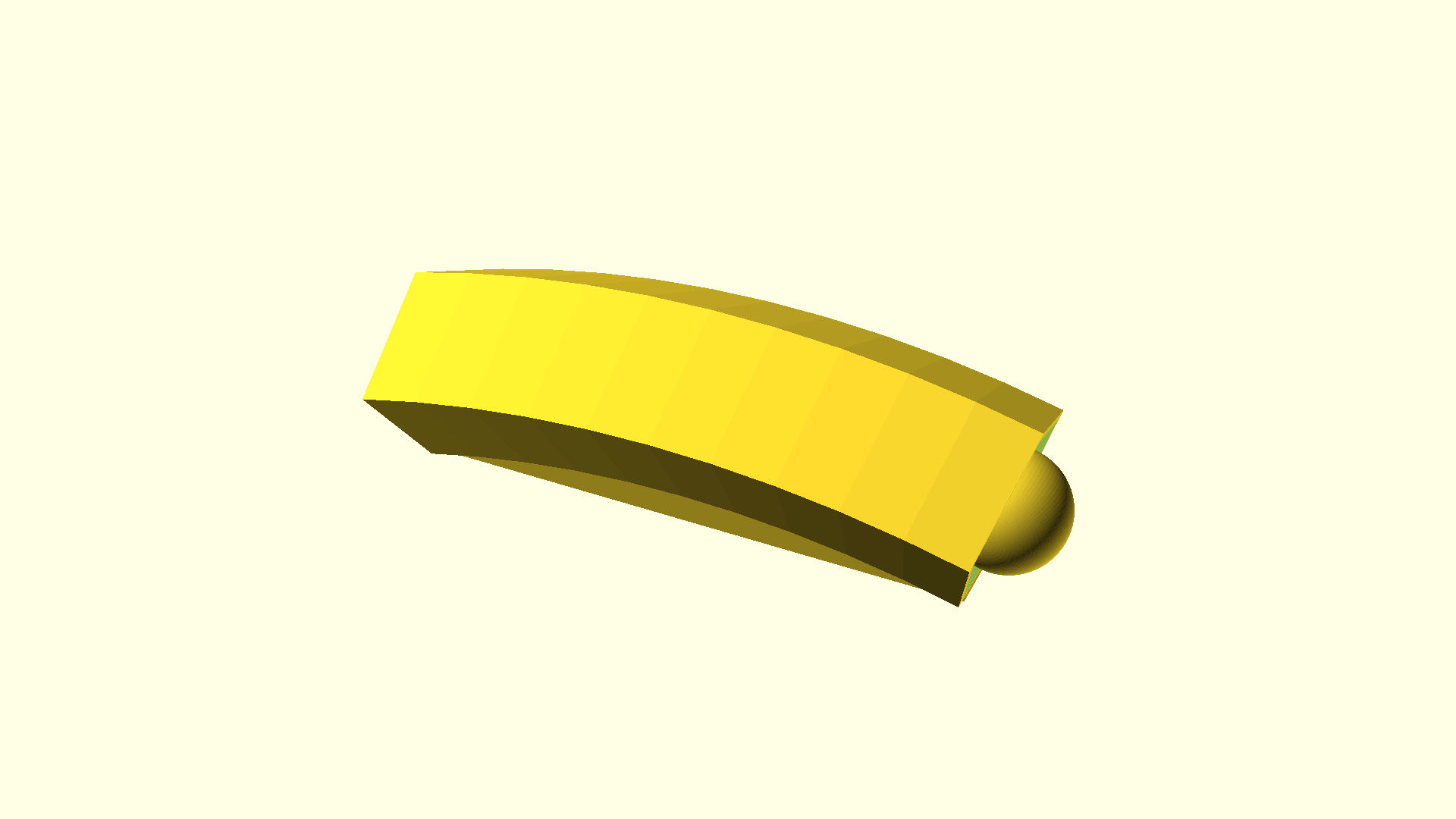
Rim section (30 degree part), 1 of 12. It has a ball and socket, as a snap fit part.
7.4 Assembly
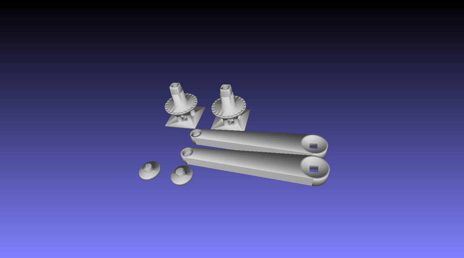
assembly.stl snapshot with meshlab showing an assortment of parts (hub split in two, cranks for mounting mountain bike pedals, and the attachment screws for
each crank)
7.5 3d printed tools for assembly

An M30 metric fastener can be tightened with these tools, using a 22mm hex allen and also around the external hex shape of the bolt.
Other tools to be used will be 6mm allen (possibly 8mm allen), and perhaps a 3d printed adjustable wrench.
7.6 Actual parts
Crank with threads for attaching mountain bike pedals.
Hub (split in two, can be mated together currently with 4 small bolts)
7.7 Print times
| Part name | Material | Print time (min) |
|
|
|
| Bearing | NylonX | 60 |
| |
Printed with NylonX on the 3d printer, Biqu BX
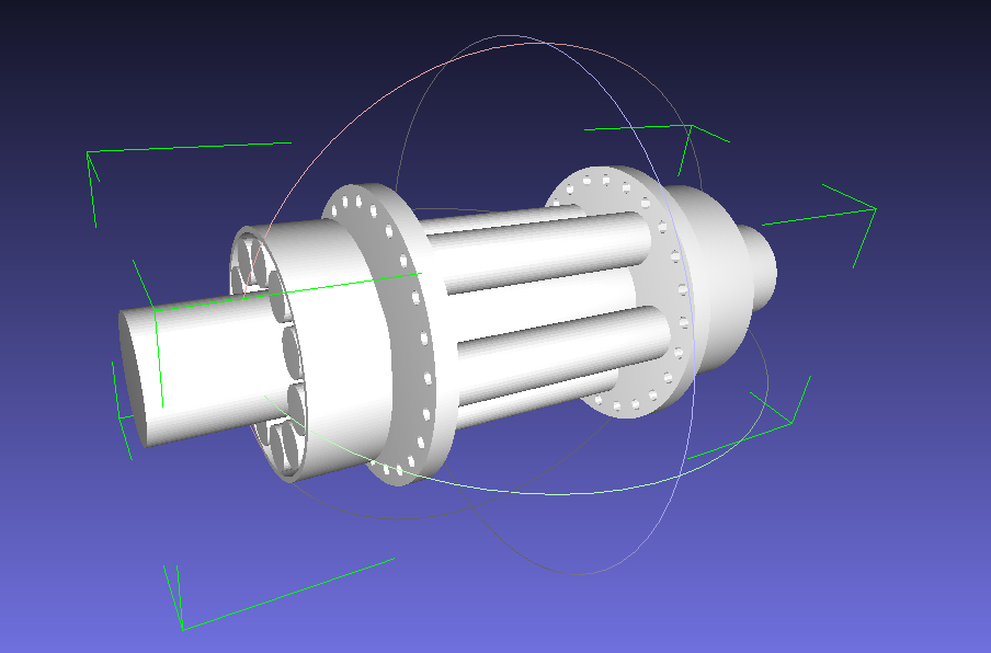
Here is a design using OpenSCAD for a 16mm diameter axle, bearings built on as well as the flanges for the spoke holes. Needs some adjustment and refinement, and
a test print with supports (vertical orientation)
7.8 Unicycle Designer
A program unicycle_designer.zip that can read a unicycle.spec file, for generating a set of base .stl files. At first, a modeler will have to be used to go through and add
various holes and threads, such as for M8 bolts.
7.8.1 Specifications
An example unicycle.spec file
wheeldiam=24
seat=0
axle=0
handle=1
wheelbearingv=0.5
pedal=170
The idea will be to have a high level main or global area of definitions, and then some sub areas such as seat, and pedal, for further customization. Wheel diameter is
in inches however the other units are millimeter.
7.8.2 Config settings
| Config setting | Type | Description | Default value |
|
|
|
|
| wheeldiam | Inches | | 24.0 |
| seat | Bool | | 0 |
| handle | Bool | | 1 |
| axle | Bool | Protruding axle on hub plates | 0 |
| wheelbearingv | Percent | Bearing rollers closer to wheel rim, or hub | 0.5 |
| pedal | Millimeter | | 170.0 |
| |
7.8.3 Templates
For example, to further test this approach a unicycle36.spec could be created with a 36” wheel diameter, seat, etc. For that model the idea would be to see what kind of
additional build volumes are available for 3d printing, so as not to split the stl model files excessively.
7.8.4 Other settings
Another setting to consider – is the bearing design on an axle, or around a set of central hub discs / plates?
At first the design will be for a larger set of bearings around a hub disc / plate.
8 Prototype videos
Video 1
Video 2
9 Future
The Lithium Ion cells, a charging circuit, speed sensor, Raspberry Pi board will be designed in and added once the basic unicycle is functional.
9.1 Electric motor
Redesign everything again with a motorized core? Gearbox?
Additional battery packs for higher voltage, motor controller, etc.
9.2 Make it closer to fully 3d printed
(Optional) If there is interest, design mountain bike pedals. Consider learning CNC machine for aluminum pedals, or trying a carbon fiber print.
(Optional) Design a seat and cut the fabric material, with suitable amount of foam to be assemebled together.
9.3 Other ideas
LED lighting to illuminate the unicycle.
10 Links